This is the case for my truffels (github.com) project — a self-hosted Bitcoin node running on a Raspberry Pi 5. I needed something that could fit an 80mm fan on top, mount a 2.9" ePaper display on the back wall, and still provide full access to all IO ports including an NVMe shield underneath. Nothing off the shelf came close, so I designed one from scratch in OpenSCAD.
The reason I needed a case in the first place? The Pi was sitting on the corner of my desk, and I kept bumping into it — causing ungraceful shutdowns on a Bitcoin node. Not ideal.
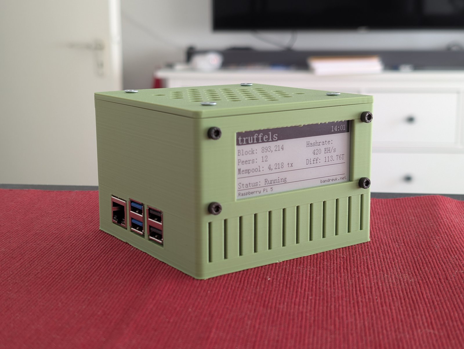
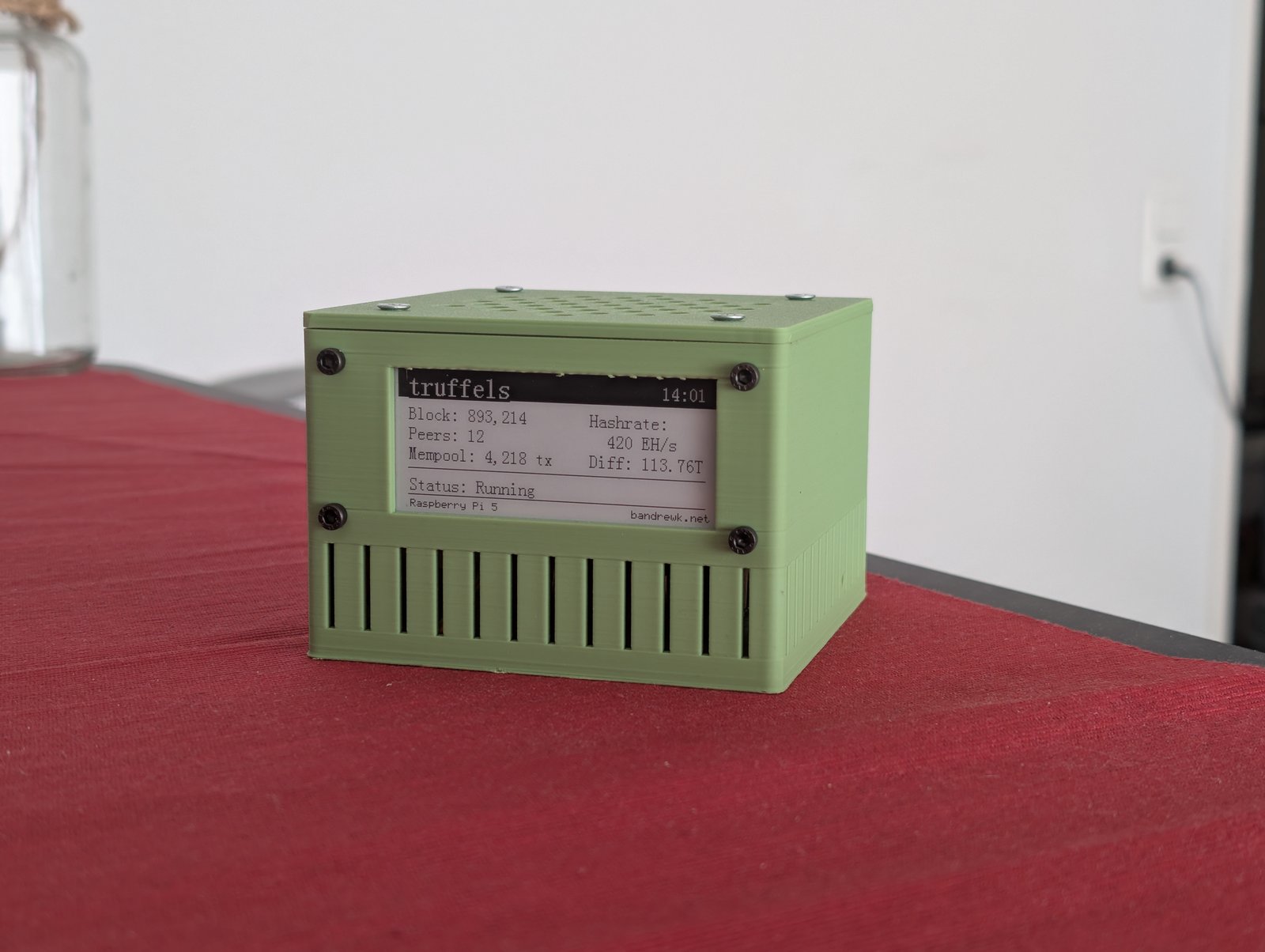
The finished v14 case with 80mm fan and ePaper display.
Goals
- 80mm fan mounted on top as intake (positive pressure cooling)
- 2.9" ePaper display visible through the back wall
- All ports accessible — USB-A, USB-C power, dual micro-HDMI, Ethernet, power button
- Recessed ports — cutouts sized for cable plugs, ports sit inside the case for protection
- NVMe shield support underneath the board
- M2.5 threaded inserts for board mounting, M3 inserts for feet
- Fully parametric — every dimension adjustable
The design
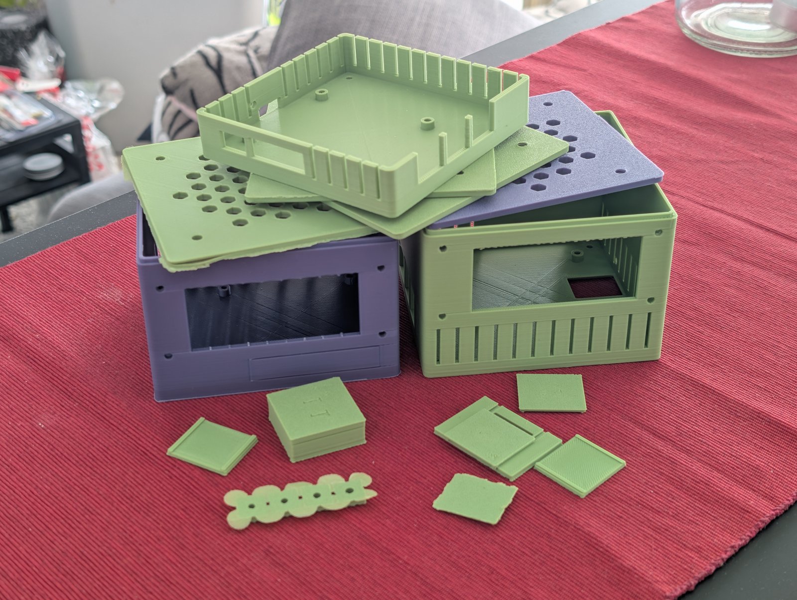
The case is split into two parts: a bottom shell with all port cutouts, standoffs, and the ePaper window, and a lid with a hexagonal air intake grid for the fan.
The fan sits on top and pushes air down onto the board. Air exhausts through the port openings and side vents — positive pressure keeps dust out.
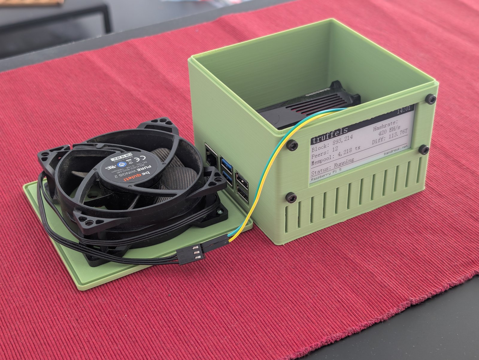
The two-part design: lid with 80mm be quiet! fan and the bottom shell with ePaper display.
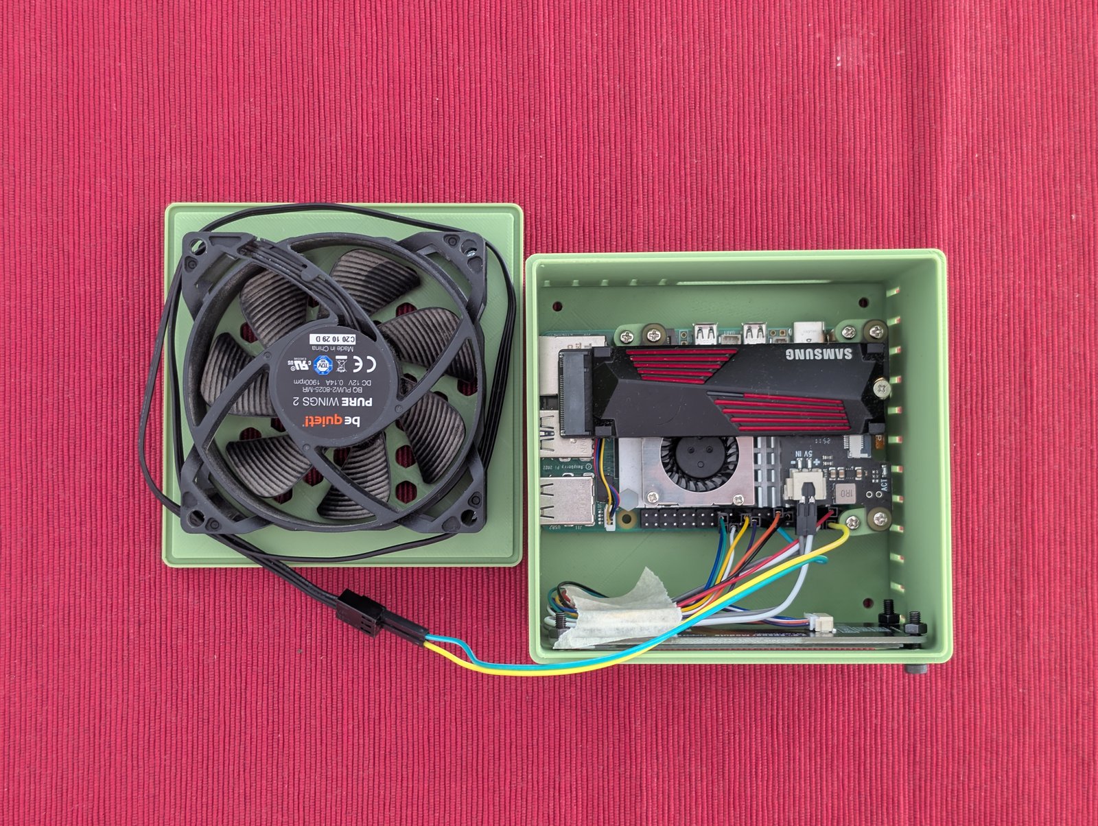
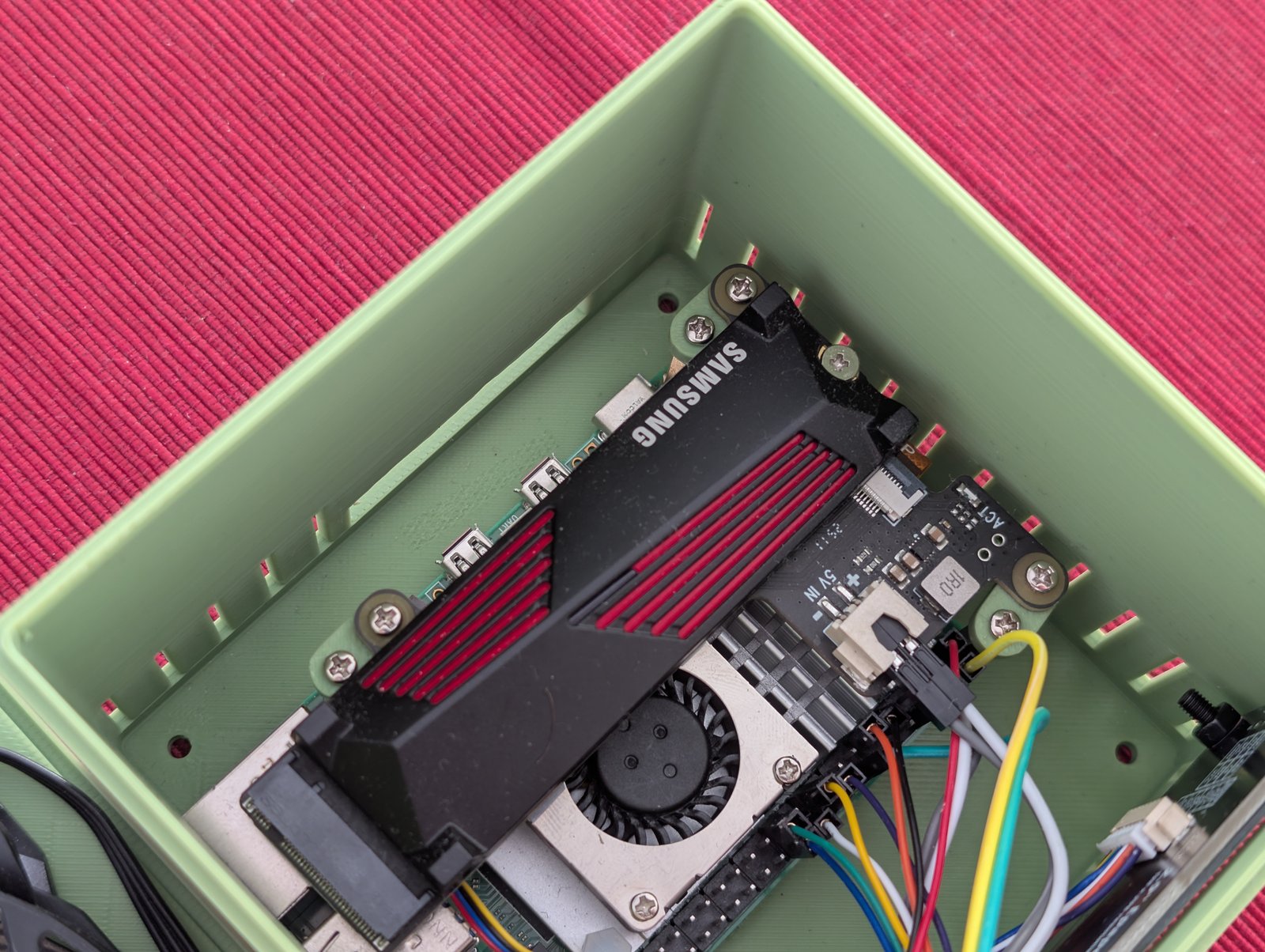
Top-down view with lid removed — Samsung NVMe, active cooler, and fan wiring visible.
The lid connects via a groove-and-lip system: a 0.8mm lip on the bottom shell slides into a matching groove on the lid. Four M3 threaded feet screw in from the bottom, each with a hex nut trap for a clean finish.
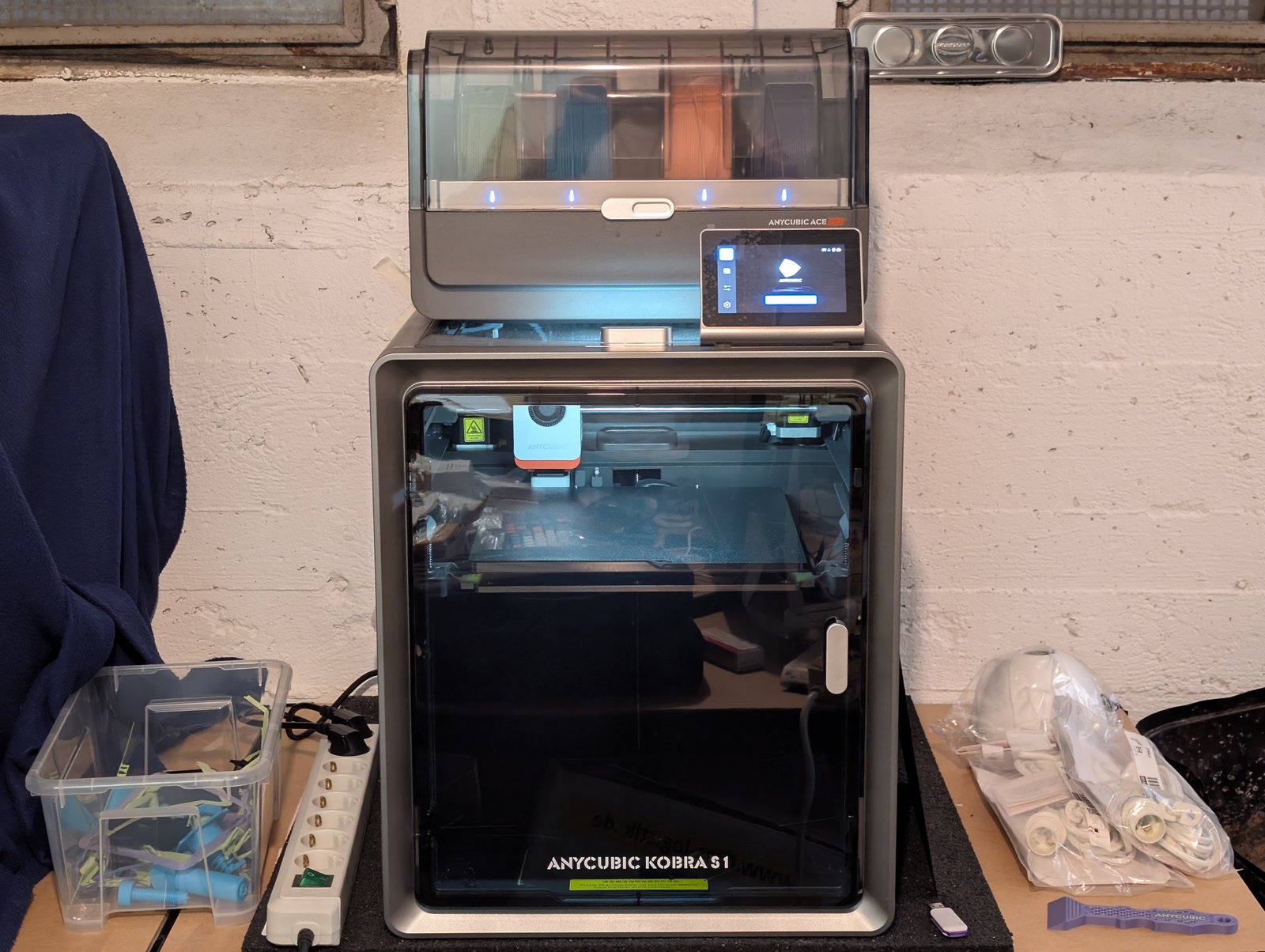
The AnyCubic Kobra S1 that printed all of this.
Print, measure, fix, repeat
Versions 1 through 9 were design iterations that never left OpenSCAD — tweaking dimensions, adding features, rearranging modules. The first physical print was v10.
v10 — first print
The first print revealed a lot:
- Ports were 2mm too deep in the case
- USB-C and HDMI cutouts too small for the cable plugs to pass through
- The ePaper display window was 3mm off-center
- GPIO breakout hole didn’t work at all
- The lid wouldn’t close
- Not enough clearance between the NVMe shield and the fan
Most of these got fixed by adjusting parameters. Port cutouts were enlarged to fit actual plug dimensions (USB-C: 13x8mm, HDMI: 28x9mm).
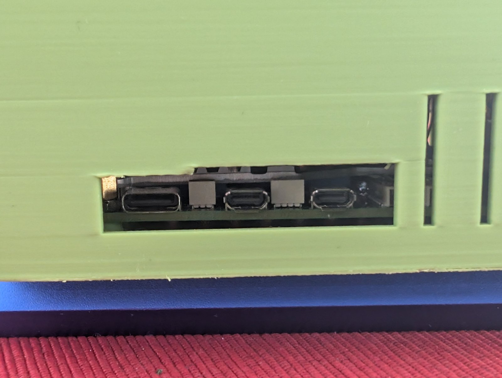
The recessed HDMI and USB-C port cutouts after resizing.
The GPIO knockout was replaced with ventilation slits. The ePaper window got extra height (epaper_extra = 14mm) to accommodate both the display and the fan above it.
v13 — second print
Closer, but still not right:
- USB and Ethernet ports needed to go 1mm higher
- The lid still wouldn’t close
- SD card hatch mechanism didn’t work
The lid issue turned out to be a geometry bug in the groove calculation. The inner block of the groove was sized as int_w + 2*lid_tol and offset by only lip — which meant it protruded into the lip space. The groove ended up exactly as wide as the lip, leaving zero clearance regardless of the tolerance parameter.
The graveyard of failed prints and tolerance test pieces — 308g of filament, roughly €2.50 worth of lessons learned.
Testing tolerances properly
Instead of guessing, I printed dedicated test objects:
- Lid tolerance test: 5 variants from 0.8mm to 1.2mm in 0.1mm steps. Winner: 1.1mm
- Insert hole test: 4 variants from 3.3mm to 3.9mm in 0.2mm steps. Winner: 3.7mm for M2.5 inserts
- Dovetail slider test: 4 variants from 0.2mm to 0.5mm. Winner: 0.3mm (ended up not using this)
Small test prints like these save hours compared to reprinting the full case each time. One lesson learned: always engrave labels on the top surface of test pieces, not the bottom — they’re unreadable otherwise.
v14 — third print (the one that works)
Applied all fixes:
- Groove geometry corrected (inner offset =
lip + lid_tol) lid_tol = 1.1mm,lip = 0.8mm(validated by test prints)- All ports raised 1mm (
port_z_offset = 1) - Standoff holes at 3.7mm for M2.5 threaded inserts
- SD card hatch disabled — access through bottom opening
One last issue: the NVMe shield extends 1mm past the USB port edge of the board. Since the board was offset 5mm toward the USB ports (to sit flush with the case wall), the shield collided with the wall.
Simple spacer adapters offset the NVMe shield by 5mm.
The fix was simple: four small spacer adapters that go between the board standoffs and the shield standoffs, pushing the shield 5mm back. 14mm long, 3mm thick, two M2.5 holes each.

HDMI and USB-C sit recessed inside the case — RJ45 and USB-A are flush with the wall.
Changelog
| Version | Type | Key changes |
|---|---|---|
| v1–v9 | Design | Initial parametric layout, fan mount, port cutouts, ePaper window, feet |
| v10 | First physical print. Fan fits, everything else needs work | |
| v11 | Design | Port cutouts enlarged, air_gap 3→6mm, epaper_extra 6→10mm, port_z_offset=2 |
| v12 | Design | epaper_extra 10→14mm |
| v13 | Second print. SD hatch and lid still broken. Board shifted +5mm toward USB side | |
| v13→v14 | Test | Lid tolerance (1.1mm), insert holes (3.7mm), dovetail slider (0.3mm, abandoned) |
| v14 | Groove geometry fixed, lid_tol=1.1, lip=0.8, port_z_offset=1, standoffs 3.7mm, NVMe spacer added. Works. |
Current status
This is a proof of concept — the case fits, the board runs stable and noticeably cooler with the 80mm fan pushing air directly onto the SoC, but it’s not done yet. Probably one or two more print iterations before I’d call it release-ready.
Basic ePaper integration works — software side is still a TODO.
Still TODO:
- Feet — designed but not yet attached to this build
- ePaper software integration — the display window is there, basic rendering works, but the truffels dashboard UI is not hooked up yet
- Final fit validation — NVMe spacers need a real-world stress test
- Potential v15 — minor tweaks once everything is assembled together for good
What I’d do differently
- Start with test objects. I should have printed tolerance tests before the first full case, not after the second failed print.
- Keep it simple. The SD card access went through three increasingly complex designs (clip hatch, dovetail slider, L-shaped cover) before I settled on just leaving an optional opening in the bottom.
- Get a deburring tool. Seriously, this thing is worth its weight in gold. It shaves off brims, cleans up edges, and removes any overhangs or print artifacts in seconds. Way faster and cleaner than a hobby knife, and you’re much less likely to cut yourself or gouge the part.
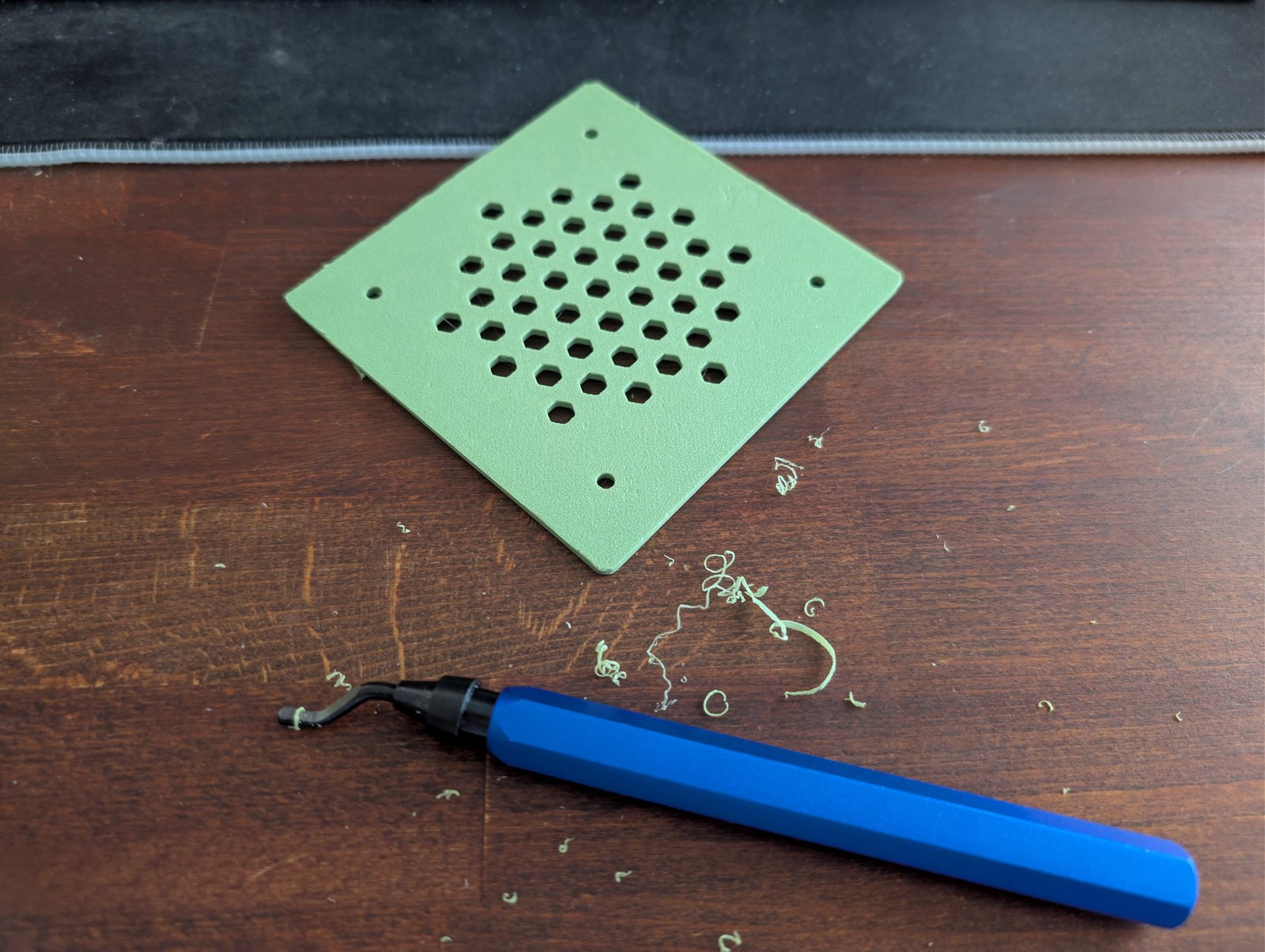
A deburring tool makes quick work of brims and rough edges.
Files
The full OpenSCAD source is parametric — wall thickness, tolerances, board position, port sizes, and fan dimensions are all adjustable at the top of the file. The design is modular: case_bottom(), case_lid(), foot(), and nvme_spacer() are independent modules that get arranged in the print layout.
Built with OpenSCAD, an AnyCubic Kobra S1, and a lot of calipers.